Solid Edge ST3 Bares All
Posted By Jon Sutcliffe On Wednesday, 13 October, 2010 @ 2:01 pm In General | Comments Disabled
Solid Edge ST3 has now been officially announced by Siemens so we are free to dive in and take a look at the hidden gems that were alluded to in our previous post “Solid Edge ST3 – The Wait Is Nearly Over” [1].
We are going to see that ST3 has some fantastic new ways of working that completely remove the barriers for users looking to adopt synchronous modelling techniques. Before we get into the main ST3 content it is worth having a quick recap on the use of synchronous prior to ST3.
When Synchronous Technology was first launched, users had a choice as to whether they started out a design using the traditional history based techniques they were used to, or the new synchronous workflow. This was based on what type of template was selected for either parts, assemblies and later, in ST2 sheet metal. Of course you could mix and match traditional and synchronous files within a complete design, and there were conversion tools to take traditional designs through to synchronous. The fact you had to make the choice to go traditional or synchronous up front also meant that you had to analyse the design up front too. This was in order to establish whether synchronous was appropriate or not. Designs that required the use of complex forms or surfaces, interpart links, family of parts, process steps, etc. were all probably best done in traditional. This in some instances created barriers for users to adopt Synchronous Technology.
Solid Edge ST3 now fulfils the vision of synchronous technology and completely removes these barriers by providing a fully integrated design environment to expand the synchronous capabilities.
Mixing Synchronous and Ordered Workflows
You no longer have to choose which modelling workflow to use up front, instead it is a simple case of switching between ordered (traditional) and synchronous whenever required. This allows synchronous to be used to very quickly start a design. Ordered features can be added later if required for more complex or process type steps. For instance ordered features can be used to add complex surfaces or blends to the existing synchronous geometry. They could also be used to document such things as the machining steps applied to a synchronous casting.
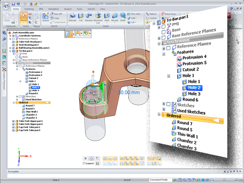
Take a look at the image above, notice that the Pathfinder is split to show both ordered and synchronous features on the same model. The really clever bit here is when it comes to making changes.
You have the same synchronous edit capabilities to adjust the part with either the steering wheel or 3D dimensions, any ordered features on the design simply recalculate and update accordingly during the edit. Believe me when I say this is a very big deal and helps to eliminate any design pre planning and allows un-planned changes to be made much more easily.
In addition to being able to switch between ordered and synchronous modelling modes, any existing models with ordered features can utilize synchronous methods when adding new geometry. Ordered features can also be selectively moved to synchronous with a simple right click. This alone will speed the adoption of synchronous and have minimal impact on any existing workflows.
On the assembly design side, it is now possible to unleash the power of synchronous with all assembly applications including wire harness design, tubing, piping, weldments, assembly features and more.
Interpart Associativity within a Synchronous Assembly
Solid Edge ST3 can establish part to part associativity within a synchronous assembly. The fundamental aspect about this is that the relationships can be created at any time in the design process, they do not need to be created up front like they would in a traditional CAD product. Interpart links can be created as we start designing, any time during the design process or even afterwards if necessary. It does not matter where the data has come from either since these relationships can be applied to imported models as easily as they can native Solid Edge models. Imagine importing a component from a supplier that uses SolidWorks or Inventor and then using it to drive your own design.
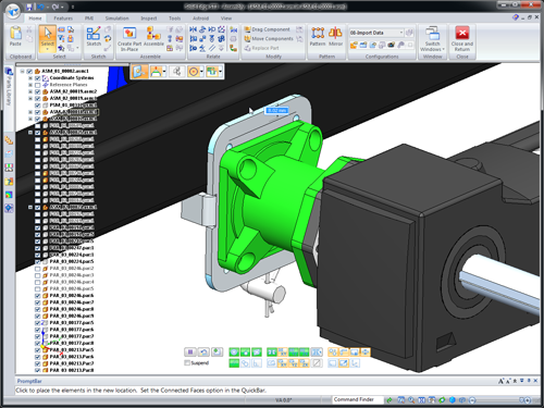
Another key point is that unlike traditional history based design where you have parent and child relationships in that one part is driving and the other part driven, in ST3, parts can be both driving and driven at the same time. Again this will allow for faster un-planned changes and make it much easier to establish how a design is linked together if you are trying to modify an assembly which was created by another user.
Solid Edge ST3 should be available to all users to download later today. Stay tuned for a look at some other new functionality as well as a more in depth look at what we have covered in this post.
Top Edging
Jon Sutcliffe
 [2]
[2]
Why not visit Solid Mastermind [2] THE Community for Solid Edge Professionals. Online Solid Edge Video training, utilities, process maps, best practices, knowledge base and much more.
Article printed from Synchronous Technology: http://www.synchronoustechnology.net/blog
URL to article: http://www.synchronoustechnology.net/blog/679/solid-edge-st3-bares-all/
URLs in this post:
[1] “Solid Edge ST3 – The Wait Is Nearly Over”: http://www.synchronoustechnology.net/blog/667/solid-edge-st3-the-wait-is-nearly-over/
[2] Image: http://www.solidmastermind.com/affiliate.html?p=ING&w=SM
Click here to print.