Solid Edge ST4 – Second Preview
Posted By Jon Sutcliffe On Tuesday, 24 May, 2011 @ 4:49 pm In General, Solid Edge User | Comments Disabled
In this second Solid Edge ST4 preview we’ll look at the remaining enhancements that we can talk about prior to the official launch announcement when the embargo on all the big ticket items will be lifted.
World Class Drafting
We’ll start with the updates to the drafting environment. This will see a brand new faster way to add special symbols to items such as text boxes, Callouts, Feature Control Frames and more. In the past we would have needed to use the Windows Character Map to do this and sometimes finding the right symbol could prove tricky. Now however ST4 will see a new dialogue for these special symbols which has logical sections enabling them to be found and used much more quickly.
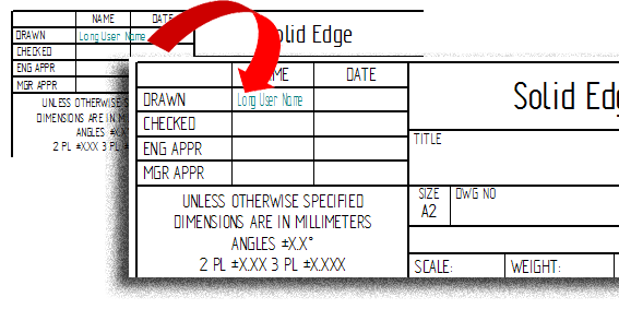
On the text side of things it will be possible to automatically fit text into small spaces. This includes the auto adjustment of the aspect ratio and wrapping of the text. This enhancement applies to Callouts, Parts List table cells and text boxes. It means that if for example we were using a callout to place property text into an area of the drawing border / title block, we could ensure that the text would always fit within a specified area.
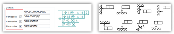
Feature Control Frames will now support the new requirements of the Y14.5 GD&T standard. In addition to this they will have a new handle which can help when defining their position within the drawing. This will assist when resizing or manipulating the break line and moving the break line around the feature control frame border. Feature control frames can also now be moved much more freely anywhere. For instance they can also be aligned perpendicular or parallel to drawing geometry as well as be attached to multiple leader lines.
Drawing views will now have the option of being locked. This is an option which can be chosen from either the Command Ribbon or the drawing view properties dialogue. Locked views will remain fixed at their current location within the drawing meaning that they can’t be accidentally dragged around. If any locked views are selected, a small glyph will display in their corner to offer a visual cue on its locked status.

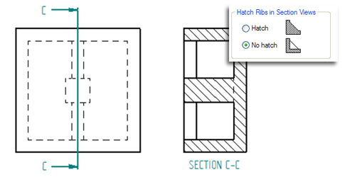
A new option for section views means that it is now possible to specify whether rib features in the model are sectioned or not. This will satisfy many drawing standards which state that ribs should not be sectioned. In the past we would have needed to remove the cross hatch detail manually. The rib section options can be controlled globally via the Solid Edge options or per view if necessary.
Whilst we’re talking about sections, it’s worth mentioning that there will be a new hatch pattern which simulates the growth rings within wood. It will be possible to have combinations of linear and radial patterns.
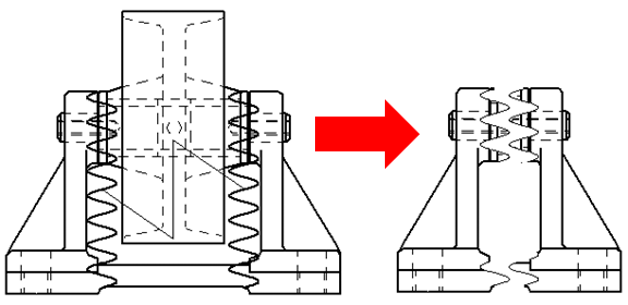
When it comes to broken views, the resulting view now has the trimmed edges of the geometry calculated and shown. This produces a far better result and means that the break lines do not appear to sit out in free space. There will be two short break line types, these will be linear and curved which will have controls for height and pitch.
Simulation
On the simulation side of things there has been some work done on the analysis of sheet metal or common thickness parts. Firstly it will be possible to manage the sheet metal gauge properties by using an Excel file. Each sheet in the Excel file can contain all of the information for a particular material type. Multiple gauges per material can be defined in order to capture the specific characteristics of the different thicknesses for each material. By using the File Locations options the Excel file can be managed centrally and shared amongst multiple users or left stand alone.
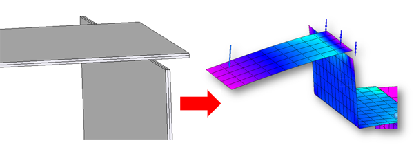
There are some new Edge and Face Glue options that will allow the simulation of more realistic scenarios with shell elements. It will handle the moment transfer between shell and solid elements and as such help where shell meshes need to be attached to other shell or indeed solid elements. This will allow the analysis of more complex situations where it is far better to use surface elements to represent a part in order to achieve better results and reduce the time it takes to mesh and calculate the results.
Finally there has been a fair amount of work done on the usability of the simulation environment. Edits within the Study Navigator can now be achieved with a simple double click. The formatting of the numerical colour bar has been improved. Single face to face connections will be quicker to define and various on screen glyphs for the contact source and target have been improved. The material table has also been overhauled and the material is linked to the sheet metal gauge.
Well that’s it for now until we can give you the full ST4 update details after the official announcement in June
Top Edging
Jon Sutcliffe
Why not visit Solid Mastermind [1] THE Community for Solid Edge Professionals.
For more information please take a look at the about [2] page.
Article printed from Synchronous Technology: http://www.synchronoustechnology.net/blog
URL to article: http://www.synchronoustechnology.net/blog/963/solid-edge-st4-second-preview/
URLs in this post:
[1] Solid Mastermind: http://www.solidmastermind.com/affiliate.html?p=ING&w=SM
[2] about: http://www.solidmastermind.com/affiliate.html?p=ING&w=SM-A
Click here to print.