Solid Edge ST3 Create 3D

Warning: Use of undefined constant home_feature_photo - assumed 'home_feature_photo' (this will throw an Error in a future version of PHP) in /home/synchron/public_html/blog/wp-content/themes/WP-MagTheme10-Prem/single.php on line 70
For some time now Solid Edge has had a tool called Create 3D which enables an imported 2D drawing to be quickly turned into a full 3D model. In previous versions Create 3D simply generated planar sketches in the 3D environment based on the detail views that came from the imported drawing. These sketches could then be used with the Solid Edge 3D commands to construct the model. This has always been a good workflow. However, the Create 3D command has been enhanced in Solid Edge ST3 to support some additional scenarios.
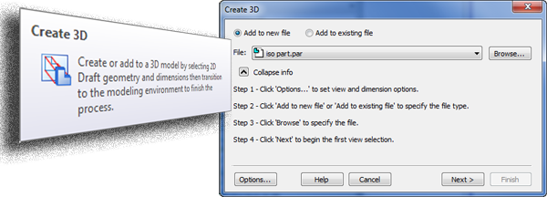
Imagine a supplier has sent you a 2D drawing of a component and the 3D model that goes with it. Unfortunately they are using a completely different CAD system so they will have had to translate the files to some sort of a neutral format so that they can be read into Solid Edge. This could be a DWG file for the 2D drawing and perhaps a STEP or Parasolid file for the 3D model. The problem with this is that once the files have been imported, they are completely unlinked. For example, any changes made to the 3D model will not automatically be reflected in the drawing. If changes are required to be made to the imported part, Solid Edge has some very flexible tools. But it would be handy to be able to use the manufacturing dimensions from the drawing since these detail the important key aspects of the part.
The Create 3D command now has a workflow that enables the drawing views and associated dimensions to not only be copied into a blank template but also into an existing part model (the imported part). Once this is done, the dimensions can be attached to the 3D geometry by simply selecting an option in the context menu. These dimensions along with Live Rules and Synchronous edits can then be used to drive the 3D model whilst automatically maintaining any design intent.
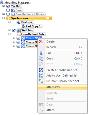
Of course once we have all this intelligence and information on the model it will be a very easy process to recreate the 2D drawing using the model complete with its dimensions. Thus re-establishing the link between model and drawing so that changes will automatically update each and every detail for us.
The video below shows the new Solid Edge ST3 Create 3D command in action.
Top Edging
Jon Sutcliffe

Why not visit Solid Mastermind THE Community for Solid Edge Professionals. Online Solid Edge Video training, utilities, process maps, best practices, knowledge base and much more.